How to Read a Hydraulic Press Guage
 A pressure estimate is a fluid intensity measurement device. Pressure level gauges are required for the set-up and tuning of fluid power machines, and are indispensable in troubleshooting them. Without pressure gauges, fluid power systems would be both unpredictable and unreliable. Gauges aid to ensure there are no leaks or pressure changes that could touch on the operating status of the hydraulic arrangement.
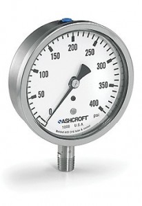
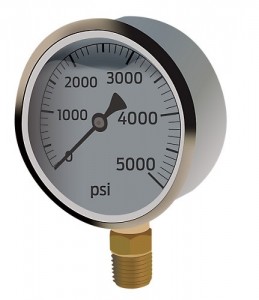
The hydraulic system is designed to work in a gear up force per unit area range so the judge must exist rated for that range. Hydraulic pressure gauges are available to measure upwards to 10,000 psi, although maximum hydraulic pressure is typically in the 3,000 to v,000 psi range. Hydraulic gauges are often installed at or near the pump'southward force per unit area port for indication of organization pressure, merely can be installed anywhere on the car where force per unit area needs to exist monitored—especially if sub-circuits operate at a pressure rate different from pump pressure level, such as after a reducing valve. Often, pressure-reducing valves accept a gauge port to tap into, allowing you lot to direct monitor its downstream force per unit area setting.
Pressure gauges have been used in fluid power systems for well over a hundred years, so it might be a surprise that pressure level gauge designs continue to evolve. The development of pressure level gauges for fluid power applications has, mostly, been an increment in awarding specific features. For instance, force per unit area gauges are now more routinely designed with hydraulic friendly pressure level connections (such as SAE/Metric directly threads) to forbid system leaks. Analog gauges with custom scales are more common and digital pressure level gauges with customizable firmware allow process measurement of pressure-based measurement of leaks or other parameters like torque, load, force and hardness.
 Pneumatic and compressed air systems are also rife with gauges, equally pressure is also measured in many locations throughout the system. Pressure is measured at the receiver(south), every bit well every bit at every FRL or stand-alone regulator in the system. Sometimes pressure level is measured at pneumatic actuators too. Typically, pneumatic force per unit area gauges are rated for not much more than than 300 psi, although typical systems run around 100 psi.
Pressure is measured in three ways—absolute, guess and vacuum. Absolute pressure level is a measure of bodily pressure including ambient air, which is nada-referenced with a perfect vacuum, but can be as high as 14.7 psi at ocean level. Accented pressure readings are considered in applications interacting with ambience air, such as the compression ratio calculation for flow (cfm) requirements. Guess pressure is zero-referenced against ambient pressure and is used in most applications operating in, but not with, ambience air, such equally in fluid ability systems. Disconnected from equipment, gauge pressure will read zero. Finally vacuum "pressure" is expressed in Torr, or referenced against ambient pressure, as with "in.-Hg" (inches of mercury) units, which measures pressure below ambient.
The hydraulic gauge can withstand different pressure ranges based on what blazon of gauge way it is and what material it is made out of. Because of this, the gauge mode and the material make up ii of the nearly of import pick criteria for gauges.
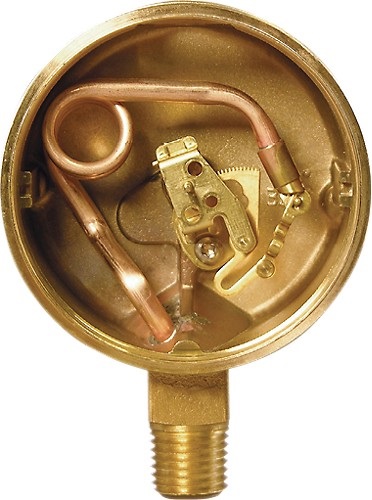
They are many types of gauge styles, the almost mutual being Bourdon tubes and bellow gauges. Bourdon tubes function past taking the pressure and converting it into mechanical energy. This energy moves a dial in the approximate, displaying the current corporeality of pressure in the system. Bourdon tube gauges are currently some of the nigh common gauges and have different configurations such as curved, helical and spiral. The unlike style of tubing, the size of the tube and the material it is made out of all vary based on the pressure range. One of import characteristic to note is the cross section of the tubing changes with increasing force per unit area. By and large, as the working pressure level of the gauge increases, the shape of the cross department of the tube's design will gradually alter from an oval shape to a circular shape.
 Bourdon tube operation is uncomplicated. They consist of a semicircular and flat tube of metal, fixed at one finish and attached to a sensitive lever mechanism at the other. As pressure increases inside the tube, the strength of the fluid attempts to straighten out the curved tube. The tube then pulls abroad from the lever, which beingness continued to the needle on the display, shows the pressure at the fluid port.
While bellow gauges role similarly to Bourdon tubes, they differ in the fact that they use a bound to judge the amount of free energy to push the dial. The spring is expanded and compressed by the pressure in the tubes and the energy created by that movement is transferred into gears that move the pressure dial.
The pressure range at which the guess will be working is a primary selection factor for the type of textile used to make the estimate. Gauges operating at higher pressures by and large tend to exist made of materials such as steel; when operating at lower pressures, they tend to be fabricated of bronze.
Most pressure gauges in North America come with a i⁄4-in. NPT male person, but SAE thread is gaining popularity. The utilise of test-point adapters at various locations on the hydraulic system allows for measurement during troubleshooting without having to buy dozens of pressure gauges. The examination-indicate fitting attaches to the gauge, which can be screwed onto the examination points throughout the circuit, assuasive you to connect under pressure to measure at various points in the system. Most gauges are 21⁄2 in. in diameter, and tin can exist either meridian-mountain or console-mount styles, but gauges are bachelor in every size, material and construction imaginable.
Whether used for testing equipment or operating machinery, the right pressure judge helps reduce costly downtime. In mechanical judge applications for hydraulic systems, the common threats to judge reliability are vibration, pulsation and pressure level spikes. Therefore, it's best to look for gauges designed specifically for hydraulic applications. These features include: a forged brass case to preclude resonant frequencies from destroying internal components; a liquid-filled case to protect the gauge from vibration and farthermost pressure cycles; and a restrictor to preclude damage to the gauge from pressure spikes. Although the liquid used in the guess varies from application to application, glycerin is commonly used and performs well in many conditions. The higher the viscosity of the liquid, the more it dampens the vibrations. When choosing between a dry, water- or glycerin-filled approximate, it is also important to consider the following: temperature range, needle response time required, changes in pressure and the amount of vibration expected from the application.
Finally, depending on the demands of the application, gauge accessories, such equally specialized restrictors, piston snubbers or even diaphragm seals, may be needed to prevent premature gauge failure.
You lot may likewise like:
Filed Under: Sensors & Gauges
Source: https://www.fluidpowerworld.com/what-are-gauges/
0 Response to "How to Read a Hydraulic Press Guage"
Post a Comment